Original Article

Affiliation:
1Department of Mechanical Engineering, Vallurupalli Nageswara Rao Vignana Jyothi Institute of Engineering and Technology, Hyderabad 500090, Telangana, India
ORCID: https://orcid.org/0009-0009-2268-3897
Affiliation:
1Department of Mechanical Engineering, Vallurupalli Nageswara Rao Vignana Jyothi Institute of Engineering and Technology, Hyderabad 500090, Telangana, India
Email: shivrajyeole@vnrvjiet.in
ORCID: https://orcid.org/0000-0003-3084-0396
Affiliation:
1Department of Mechanical Engineering, Vallurupalli Nageswara Rao Vignana Jyothi Institute of Engineering and Technology, Hyderabad 500090, Telangana, India
ORCID: https://orcid.org/0000-0002-4947-7745
Affiliation:
1Department of Mechanical Engineering, Vallurupalli Nageswara Rao Vignana Jyothi Institute of Engineering and Technology, Hyderabad 500090, Telangana, India
ORCID: https://orcid.org/0000-0002-5752-2761
Affiliation:
2Orthopaedic Specialty, Namasvi Speciality Clinics, Hyderabad 500090, Telangana, India
ORCID: https://orcid.org/0009-0007-0117-1409
Explor Med. 2023;4:1033–1047 DOI: https://doi.org/10.37349/emed.2023.00193
Received: July 13, 2023 Accepted: September 20, 2023 Published: December 28, 2023
Academic Editor: Nermeen A. Elkasabgy, Cairo University Faculty of Pharmacy, Egypt
The article belongs to the special issue Exploration of 3D and 4D Printing in the Biomedical and Personalized Medicine Fields: Merits and Challenges
Aim: Arthritis is a degenerative condition characterized by the progressive deterioration of the knee joint, leading to aches, rigidity, and decreased mobility. Total knee arthroplasty (TKA) surgery is performed to alleviate pain for restoring activity in these patients. TKA is carried out due to natural wear of the cartilage and meniscus or by sudden impact at the knee joint area. The surgical procedure involves careful planning, precise bone cuts, and insertion of artificial components made of metal alloys and high-density polyethylene. However, conventional manufacturing of customized knee implants involves time and cost. This work aims to present the application of three-dimensional (3D) printing for developing individualized knee implants for TKA and the challenges faced during it.
Methods: Morphometry of the knee joint varies among different populations, including Indian and Western, which pose challenges during the surgery as accurate alignment and implant sizing are crucial for optimal outcomes. A female patient’s pre-surgery computed tomography (CT) scan is considered to identify the disease and to find region of interest (ROI) such as knee joint. Process involves converting scanned data to a file format for 3D printing via computer-aided design (CAD).
Results: The patient’s CT scan data is processed to obtain the CAD models of knee joint and standard triangulation language (STL) file. Additional geometries and noise present near the region are removed to get ROI. Open loops and overlapping triangles are rectified in the STL file. Based on the morphometry of the bone, resection is done to obtain the CAD models of knee implants. 3D printing of the knee joint and implant prototypes is then obtained using fused deposition modelling (FDM). Line layers on the printed implant prototype are seen.
Conclusions: Patient-specific 3D printed knee joint implant prototypes are successfully obtained using FDM. Challenges faced during the work are successfully worked out.
Arthritis of knee has become a prevalent ailment among humans. Osteoarthritis, rheumatoid arthritis, and post-traumatic arthritis are the types of arthritis that commonly affect the knee joint and its adjacent areas [1]. Over the past 40 years, knee replacement surgeries have become more common, and their use has increased worldwide [2]. A patient might require a total knee replacement (TKR) due to a number of circumstances. Osteoarthritis symptoms include cartilage degeneration, bone degradation, swelling of the joint with newly produced bone, and moderate synovial membrane inflammation [3]. TKR aka knee arthroplasty is a surgery for remedying knee osteoarthritis. It is reported that up to 25% of patients are dissatisfied with their functional results after surgery. Total knee arthroplasty (TKA) surgery often fails due to implant misalignment. The anatomical mismatch between the prosthetic components and the anatomies of various individuals has been identified as another source of patient discontent [4]. Although injuries may be avoided, a thorough study of the knee anatomy and how injuries develop, as well as their prevention and occurrence, can aid in the diagnosis of a patient [5]. A direct impact to the knee can be dangerous and needs quick medical attention [6]. It is reported that the survival rate of individual prosthesis is 10-year with more than 95% probability. Fundamentally, TKA requires individualised and precise bone cuts with prosthetic component implantation. The aim is to reinstate the neutral mechanical orientation of the lower extremity for uniformly distributing load in the knee joint thereby decreasing the wear of the polyethylene liner and extending the endurance of the TKA prosthesis [7]. Three-dimensional (3D) printing has been growing as a popular choice in the medical fraternity, especially in the orthopaedics and trauma surgeries, due to the rapid and innovative advances in care and surgery [8]. Patients can improve their quality of life by restoring a good range of motion and reducing pain with artificial joint reconstruction. There has been an increase in the primary arthroplasties and related complications like periprosthetic osteolysis, aseptic loosening, periprosthetic fractures, and periprosthetic infections [9]. TKA achieves a patient satisfaction rate of 75% to 89%, and about 50% of patients experience postoperative functional limitations and infections. Causes of extra-articular wear are found to be micro-motion between the TKR tibial bearing and the metal base plate (reverse wear) as well as impulse of the ultra-high-molecular-weight polyethylene (UHMWPE) bearing against raw cement or hip and knee osteophytes [10].
The tibia tray has been a notable complication in TKA since 1984. It has been shown that metallurgy and stress rise have both contributed to tray fracture. A body mass index (BMI) of 37 kg/m2, which was distributed heavily in the posterior thigh and calf areas, increased the load on the tibial tray as well as caused the posterior tibia to be loaded [11]. Fatigue fractures were majorly caused by a lack of bone support during the first implantation, most likely resulting from osteolysis. It is important to focus on the precise positioning of each component during the initial process [12]. The tibial component broke at the intersection of the base plate and stem resulting in total dissociation between the two parts. Clinicians should be cautious regarding catastrophic failure because this unusual occurrence is difficult to detect in radiography and necessitates careful observation for evidence of component subsidence [13]. There is a new modular design with a titanium alloy tray covered with a porous tantalum layer (trabecular metal) and a separate UHMWPE insert [14]. Due to failed knee arthroplasty, revision arthroplasty has become a significant clinical issue. Polyethylene wear, osteolysis, and material fatigue are the major causes of implant failure [15]. Microscopic study of the tissue beneath the broken portion of the tibial base plate disclosed a darkly stained metallic deposit that was verified to be tantalum and titanium by micro-proton induced X-ray emission (PIXE). The tibial plate fracture fits the requirements for a typical fatigue fracture, according to fractographic analysis and stress testing [16]. The patellar and femoral components were examined intraoperatively and found to have good bone fixation, requiring no alteration. A coronally oriented fracture was observed in the posteromedial tibial baseplate with little ingrowth. The polyethylene liner was also damaged, and the locking mechanism was rendered inoperable. The Anderson Orthopaedic Research Institute classified the osseous injury as a type 2A bone defect since it was localised to the medial tibial condyle. The osseous defect was filled with a tibial reaming autologous transplant. Fractured tibial components in both cemented and uncemented models, osteolysis, and long-term polyethylene wear were recognised as the predominant reasons for implant failure [17]. After the failure of cementless models, screw-based fixation was replaced by anchored tibial models as it eliminated screw holes and provided a larger surface area for implant fixation. As a result of this, the potential sites of osteolysis are eliminated. According to the report of the Australian National Joint Replacement Registry (ANJRR), only 9 patients (1.7%) needed revision knee arthroplasty out of 492 recorded cases, and all received revision surgery between 12 and 36 months after the initial procedure [18]. Nylon 645 polymer was developed specifically for the fabrication of biologically inert implants utilising typical fusion coating manufacturing procedures with 3D printers. This material has been used to make bespoke implants to repair damaged cartilage in the knee [19]. The edge-only ungrounded model has the greatest total damage points and line wear rate. No variations were reported in damage and wear amongst the other TKA designs. However, this inference may be used with caution due to the limited sample size [20]. The use of computer-guided TKA and patient-specific equipment increases TKA prosthesis insertion accuracy and results in the optimal positioning of mechanical axis at the postoperative lower extremity. Even though image-based preoperative planning can assist in mending of neutral mechanical alignment of the lower limb, it does not visibly depict the load and stress distribution of the TKA knee and does not consistently foresee TKA prosthesis retention [7]. The aim of the work is to extract patient anatomical properties of the knee joint using medical software, model patient-specific knee implants, and develop 3D printed implants for TKA using fused deposition modelling (FDM) 3D printer.
Femur bone, tibia bone, and kneecap (patella) constitute a knee joint. A smooth substance called articular cartilage protects the ends of these bones allowing them to move easily within the joint. In between the femur and the tibia, C-shaped wedges called menisci are present which serve as shock absorbers for the joint [21]. The knee is commonly thought to be made up of the tibiofemoral and patellofemoral joints. The knee joint is depicted in Figure 1. The tibiofemoral joint is separated into medial and lateral divisions [22]. There is a slight difference in cross-sectional size among lateral and medial condyles, but the former condyle is constant. When flexion occurs, the femoral and tibial condyles can slide and roll together [23].
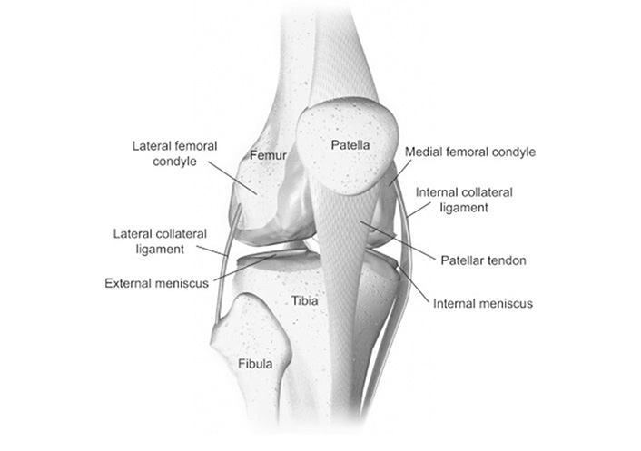
Anatomy of knee [24]
Note. Reprinted with permission from “Biomechanics of the knee,” by Affatato S. In: Affatato S, editor. Surgical techniques in total knee arthroplasty and alternative procedures. Cambridge: Woodhead Publishing; 2015. pp. 17–35 (https://www.sciencedirect.com/science/article/abs/pii/B9781782420309500026). © 2015 Elsevier Ltd.
Diseased bone and cartilage are removed in a TKR surgery. Femur distal and tibial bones are cut and reshaped to suit the femoral part and tibia tray of the prosthesis [25]. The femoral, the tibial, and the patella are the three basic components. As indicated in Figure 2, the tibial and patellar components could be solid polyethylene or have a metal backing that supports a polyethylene articulating surface [26].
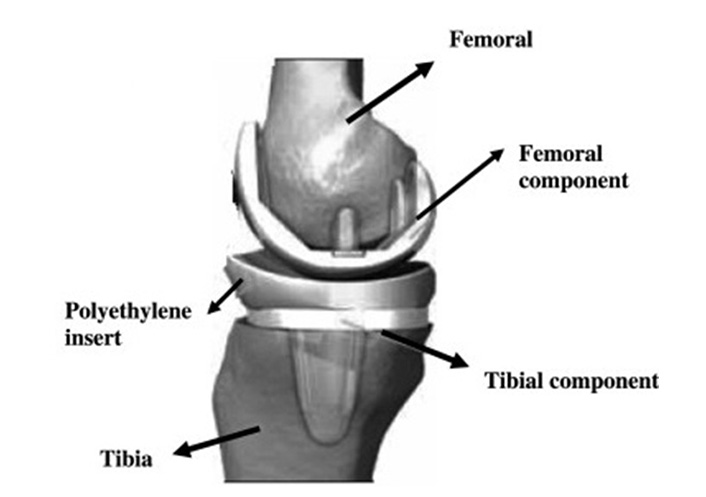
Components of TKA [27]
Note. Adapted with permission from “Ti based biomaterials, the ultimate choice for orthopaedic implants – a review,” by Geetha M, Singh AK, Asokamani R, Gogia AK. Prog Mater Sci. 2009;54:397–425 (https://www.sciencedirect.com/science/article/abs/pii/S0079642508001126). © 2008 Elsevier Ltd.
TKA is commonly performed when the cartilage is injured, the joint is distorted, and worn cartilaginous bearing surfaces need to be replaced with artificial bearings [28]. The goal of arthroplasty is not to treat illness but rather to mechanically address a biological problem. Arthroplasties may be the only treatment for individuals with significant joint injury [29]. Obese individuals using TKA seems to have larger functional improvements than those with a normal BMI [30, 31]. However, the functional results of TKA can be enhanced by focusing on managing the patient’s excess weight concerns [32]. TKA resulted in weight reduction, better BMI, and functional results in 31% of instances [33]. On 781 patients, revision TKAs have been performed. Loosening (39.9%), infection (27.4%), instability (7.5%), periprosthetic fracture (4.7%), and arthrofibrosis (4.5%) are among the most common reasons for failure. Aseptic loosening, infection, instability, periprosthetic fracture, and arthrofibrosis are the typical causes of repeated TKA failures [34].
3D printing process produces objects using printing-based technology. It belongs to the material extrusion category in additive manufacturing (AM). This approach involves depositing the material selectively through a nozzle [35]. AM involves the creation of products from computer-aided design (CAD) data layer-by-layer using additive techniques [36]. Biomedical devices and tissue engineering (TE) benefit greatly from 3D printing due to its ability to manufacture low-volume or one-of-a-kind parts depending on patient-specific needs [37, 38]. FDM is an additive technology in which basic material is melted and moulded to produce new shapes. The nozzle acts as a guide and extrudes material precisely laying one layer over the other [39]. Generally used filament material types in FDM are polylactic acid (PLA), polyvinyl alcohol (PVA), acrylonitrile butadiene styrene (ABS), thermoplastic elastomer (TPE), polycarbonate (PC), and PLA with graphene [40].
Around 80% of medical implants are metallic and further classified as bio-degradable and non-degradable metallic implants. Metals, polymers, ceramics, and composites are employed in orthopaedic implants [41]. Fifty metallic alloys such as titanium (Ti) alloys, nickel (Ni) alloys, aluminum (Al) alloys, copper (Cu) alloys, tool steels, stainless steels, cobalt-chromium (Co-Cr) alloys, and refractory metals are employed in AM [42]. AM allows the fabrication of customized prosthetic patient-specific implants based on their size, shape, and mechanical qualities [43]. A variety of materials can be used in 3D printing like ABS plastic, PLA, polyamide (nylon), glass filled polyamide, epoxy resins (epoxy resins), silver, titanium, steel, wax, photopolymers, PC, cells, hydrogels, etc. Femur and tibia bones are made of cobalt, chromium, and molybdenum alloys [44, 45]. A spacer set consists of a femoral spacer, a tibial spacer, and a canal rod. UHMWPE spacers have been tested for biocompatibility [46]. The femoral component made of Co-Cr is 3D printed using selective laser melting. Titanium-aluminium-vanadium alloy (Ti6Al4V) and conventional polyethylene are used to make the tibia and tibial implants, respectively [47]. Due to their equivalent density with the human bone, magnesium alloys offer the highest biomechanical compatibility and generate the least degree of discomfort in comparison to stainless steel or titanium alloys [48].
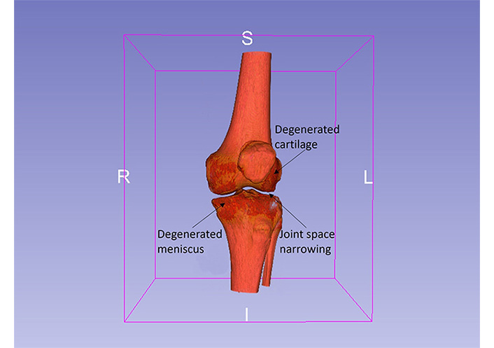
Several softwares are available for identifying diseases and injuries. 3D Slicer v5.2.1 is an open-source software (www.slicer.org) which employs volume rendering as a visualization approach for displaying picture volumes as 3D objects. The visualization of a patient suffering from knee joint with degenerated cartilage and meniscus is depicted in Figure 3. A healthy knee joint has normal space among the femur and tibia bone, however, in an osteoarthritis knee, the joint space narrows with the breaking down of cartilage and damage of the meniscus [49, 50].
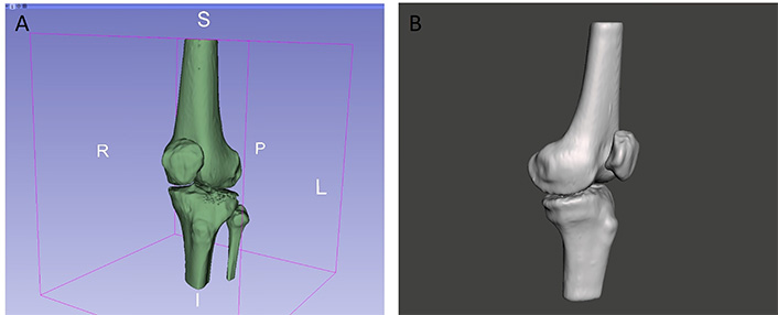
The knee joint of a 42-year-old lady suffering from osteoarthritis of the left knee is obtained using a computed tomography (CT) scan of transmissive type as shown in Figure 4A. In CT, images are stored in digital imaging and communications in medicine (DICOM) format by the devices. Using 3D Slicer v5.2.1 software, a complete set of images of the knee joint are separated by changing threshold values. The threshold values are set from 152 to 2,923.60 as exhibited in Figure 4B. With the help of Segment Editor tools, the model is edited to remove additional geometries and noise factors such as muscles surrounded by bone, as shown in Figure 5A. Segment Editor is a module in 3D Slicer v5.2.1 software that is used for specifying segments (structures of interest) in 2D/3D/4D images. It offers editing of overlapping segments, display in both 2D and 3D views, fine-grained visualization options, editing in 3D views, create segmentation by interpolating or extrapolating segmentation on a few slices, editing on slices in any orientation [51]. The anatomical features of the knee joint are obtained. The segmented DICOM file is then switched to a standard triangulation language (STL) file as shown in Figure 5B. Autodesk Meshmixer v3.5 (Autodesk Inc., San Rafael, CA, USA) software is used to identify the errors like open loops in the STL file as demonstrated in Figure 5C.
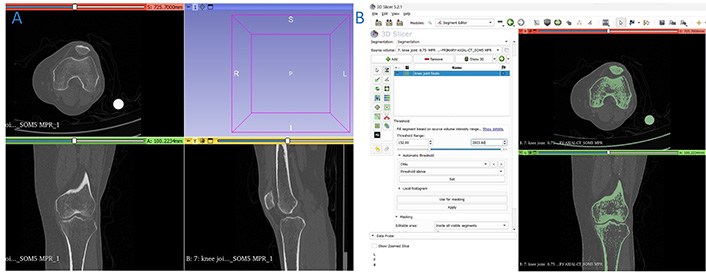
Knee joint. (A) CT scan images in DICOM format; (B) thresholding range of knee joint
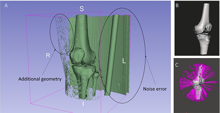
Editing of knee joint model. (A) Additional geometry at knee joint; (B) exported STL file; (C) open loop identified
Post-repairing and optimization of the mesh are carried out using appropriate tools. 3D printing is performed on the FDM based Flashforge Guider II (Zhejiang Flashforge, 3D Technology Co. Ltd., Jinhua, Zhejiang, China). FDM is capable of 3D printing using different materials [52]. The working principles of FDM and Flashforge Guider II printer are illustrated in Figure 6.
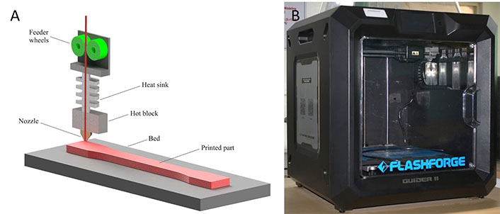
FDM technology. (A) FDM printing process; (B) Flashforge Guider II
Note. Figure 6A adapted from “On the post-processing of 3D-printed ABS parts,” by Khosravani MR, Schüürmann J, Berto F, Reinicke T. Polymers. 2021;13:1559 (https://www.mdpi.com/2073-4360/13/10/1559). CC BY.
Flashforge Flashprint v5.6.1 (Zhejiang Flashforge 3D Technology Co. Ltd., Jinhua, Zhejiang, China) software is employed for setting print parameters and slicing of the STL file where the 3D model is imported. The knee joint’s orientation is changed inside the print area. The printing variables are disclosed in Table 1.
Printing variables
| Material type | Layer height (mm) | Number of shells | Infill (%) | Infill type | Build time | Support structure |
|---|---|---|---|---|---|---|
| PLA | 0.2 | 2 | 20 | Hexagonal | 8 h 36 min | Added |
STL file of the knee joint cannot be used for designing knee joint prosthetics directly in any CAD software. For processing of the STL file into the standard for the exchange of product data (STEP) file, knee joints are made into individual bone segments like femur, tibia, fibula, and patella. The individual STL and STEP files of the knee joint are shown in Figure 7. Conversion of STL to STEP files is carried out using Hypermesh v17.0 (Altair Engineering Inc., Troy, MI, USA) and Autodesk Meshmixer v3.5 softwares. STEP file is later imported into Autodesk Fusion 360 v2.0 (Autodesk Inc., San Rafael, CA, USA) software. These imported files are used for altering the part and adding materials to it.
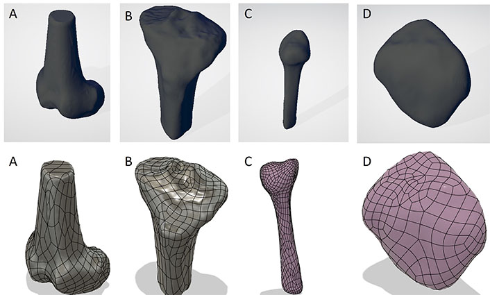
Individual STL and STEP files of knee. (A) Femur; (B) tibia; (C) fibula; (D) patella
Bone resection in CAD involves removal of bone wherein the resurfaced bone model utilized for constructing the patient-specific knee component is used for conducting an examination of off-the-shelf knee components [53].
There are three standard sizes for resection of the knee joint based on femur geometry where resection will take place. Size groups of femoral anterior-posterior (A-P) length are shown in Table 2 [53]. The measurement of A-P length is shown in Figure 8A. Femurs’ medial anterior posterior (APM) length is 53.351 mm and lateral anterior posterior (APL) length is 56.796 mm. The average length of A-P is found to be 55.072 mm which falls under the small category. When the “knee angle” (tibio-femoral angle) is 6° valgus, the knee is in neutral mechanical alignment. The femur is traditionally cut using an intramedullary reference system guided by the medullary canal, which is also the anatomic axis. The guide is set at an angle of roughly 6° between anatomic and mechanical axes. The depth of the distal femur is 9 mm. As a result, the distal femoral cut’s desired depth is 9 mm [54, 55]. Based on its small size, the average thickness of the bone resection in the ConforMIS CR implant (Conformis, Inc., Bedford, MA, USA) resection of distal medial and distal lateral thickness is 6.5 mm. The posterior medial and posterior lateral thicknesses are 5.9 mm and 5.8 mm, respectively. The resection of the femur bone can be seen in Figure 8B. Both the mechanical and the anatomical axes are parallel, therefore the tibia is cut at an angle of 0°. The joint line is unchanged if 11 mm of tibial bone is removed. This allows for a larger polyethylene liner of 11 mm instead of 9 mm, to be placed. The resection of tibia bone is shown in Figure 8C.
Classification of knee based on sizes [53]
| Sizes group | A-P length |
|---|---|
| Small | 53–56 mm |
| Medium | 61–63 mm |
| Large | 74–76 mm |
Note. Adapted from “Bone preservation in a novel patient specific total knee replacement,” by Kurtz WB, Slamin JE, Doody SW. Reconstr Rev. 2016;6:23–9 (https://reconstructivereview.org/ojs/index.php/rr/article/view/133). CC BY-NC.
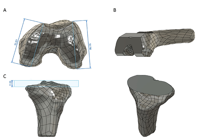
Resection of femur and tibia bones. (A) APM and APL; (B) resection of femur bone; (C) resection of tibia bone. All dimensions are in mm
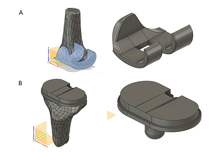
Autodesk Fusion 360 v2.0 is used for modelling patient-specific implants. The implant design is evolved from the profile of femoral bone resection and ConforMIS implants, which gave average implant thickness values. Using those values, modelling of the implant has been done. The models of femoral implants are shown in Figure 9A. The tibial implant is created based on the profile of the tibia bone. With a resection of 9 mm tibia bone, a resection profile has been created on the top surface. The laying of liner exactly into the tibia tray is shown in Figure 9B. The liner and tibial tray are extruded by 9 mm and 4 mm respectively and a shell of 2 mm is created for laying the liner on it.
Knee implant files are imported into Flashprint v5.6.1 software where the process parameters are set for 3D printing. Slicing is performed after the addition of support structures on the femoral implant and tibia tray. Verification is carried out on knee implants. 3D printing process parameters are provided in Table 3. Flashprint v5.6.1 software generates the G-codes and is exported to Flashforge 3D printer for printing.
Input parameters
| Material type | Layer height (mm) | Number of shells | Infill (%) | Infill type | Build time for femur & liner implant | Build time for tibia tray | Support structure |
|---|---|---|---|---|---|---|---|
| PLA | 0.20 mm | 2 | 25% | Hexagonal | 2 h 58 min | 55 min | Added |
The imported files of DICOM data in 3D Slicer v5.2.1 software as well as the thresholding value are shown in Figure 4. The thresholding is set at 152 and 2,923.60 for upper and lower values respectively for better visualization of the bone. As shown in Figures 5A and 10A respectively, additional geometries are removed using scissoring and smoothing tools. Scissoring helps in the removal of major visible geometry while smoothing helps in the removal of invisible geometry. Open loops present at the knee joint region during conversion from DICOM to STL file are identified and rectified using Autodesk Meshmixer v3.5 software as shown in Figures 5C and 10B respectively.
Error and noise rectification. (A) Removal of additional geometries; (B) error rectified STL file of knee joint
STL file of knee joint is imported in Flashprint v5.6.1 software. Different orientations are tried to achieve minimum support to the knee joint, better accuracy, and a good surface finish. The layer height of 0.20 mm, 20% infill with hexagonal pattern, and 2 shells are employed for printing of knee joint. It took 8 h and 36 min to print with supports using PLA material since it is biodegradable. A 3D printed knee joint prototype after the removal of support structures are shown in Figure 11A and 11B. Knee implants-femoral, tibial, and liner are 3D printed using PLA material in Flashforge FDM printer using the layer height of 0.20 mm, 25% infill with hexagonal pattern, and 2 shells as shown in Figure 11C–E. It took 2 h and 58 min for printing the femur and liner whereas 55 min for the tibia tray. The printed assembly components are shown in Figure 11F.
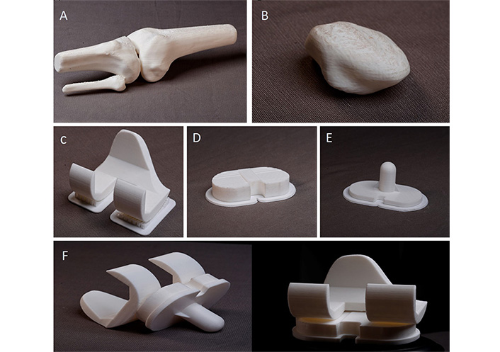
3D printed prototypes. (A) Knee joint; (B) patella; (C) femur implant; (D) tibial tray; (E) liner; (F) assembly of knee implants
Arthritis of the knee joint is a deteriorating disease which worsens with age thereby causing severe pain, stiffness, and decreased mobility among patients. To alleviate this, TKA surgery is usually recommended. Commercially available conventional implants are used in such surgeries which are costly as well as not as per the patient-specific needs. This work aimed at exploring the possibility of utilizing 3D printing technology in the development of patient-specific knee joint implants and challenges faced if any. A 42-year-old female with osteoarthritis was chosen as the subject for this explorative study. The doctor recommended TKA surgery. CT scan data of the patient is acquired in DICOM format, and processed in 3D Slicer v5.2.1 software. It is to be noted that while performing segmentation in the 3D Slicer v5.2.1 software, the thresholding range will vary and will not give the exact region of interest, hence it must be set either by lowering or raising the thresholding value. Additional geometries need to be removed using the scissoring tool. A smoothing tool is used to smooth the outer surface of the knee joint. Scissoring helps in removing major visible geometry whereas smoothing helps in removing invisible geometry as shown in Figure 10A. The conversion process from DICOM to STL file led to open loops which are identified and rectified using Autodesk Meshmixer v3.5 as depicted in Figure 10B. STL files of knee joints are converted to STEP files using Hypermesh v17.0 and Autodesk Meshmixer v3.5 software. Parts are altered using Autodesk Fusion 360 v2.0 software. The morphometric A-P length of the femur classifies the knee size. The patient data utilized in this work falls under the small size category. The femur bone is resected based on the average resection of the bone as per ConforMIS samples. Average implant thickness values are obtained from the implant design evolved based on the profile and ConforMIS CR. The tibia bone is removed by 11 mm, which allows the tray to hold a larger piece of polyethylene (9 mm). The tibial implant and liner are created as per the profile of the tibia bone. Based on the final STL file obtained, the prototype of the knee joint is printed using PLA material in FDM 3D printer. Various issues faced during this process like additional geometries captured during the scan, modelling of femur and tibia bone head, the rectification of STL errors, and additional line layers in 3D printed models are successfully resolved. Knee joint bone resection is done as per the standard guidelines to obtain a knee implant prototype using the FDM 3D printing technique. Challenges faced during the execution of this study are discussed below:
Human bones have complex and intricate profiles, especially contours of the knee joint, which cannot be modelled directly using CAD tools. Such profiles can be modelled using CT scans under the reverse engineering method. The extracted CT scan data has a series of processing steps to get the ultimate STEP file of the knee joint. The STEP file is used for adding and altering knee joints in CAD software. For the design of a customised knee implant, bone resection is carried out as per the standards mentioned in Table 2. It is noteworthy to mention that the greater the profile complexity of the femur and tibia implants, the more stable should be the profile of the implant as well as its alignment in the femur and tibia bones. These scans are so sensitive that they capture additional geometries and noise which need to be removed later. As discussed earlier and exhibited in Figures 4B and 5A, additional geometries and noise like muscles surrounding the bone are removed using various tools available in 3D Slicer v5.2.1 software.
Conversion of CAD model to STL file also leads to the generation of errors. Open loop and overlapping triangle STL errors rectified using Autodesk Meshmixer v3.5 software are depicted in Figure 5C.
Modelling of the medial and lateral sides of the femur bone for resection also involves complexity. As both sides vary in dimensions depending upon the measurement of the profile, Loft tools in CAD software need to be used to address this challenge.
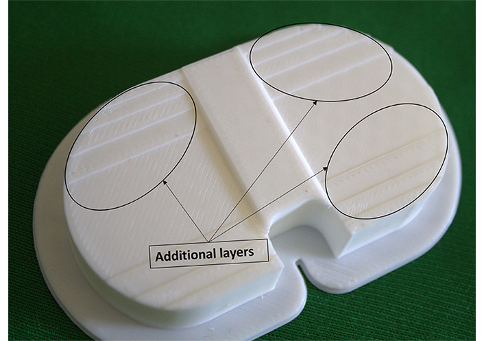
3D printing of implants also presented challenges. In this work, even after model corrections as well as defining the best settings for printing, additional layers or line marks are visible on the implant as depicted in Figure 12. These are removed by sanding and polishing of the surfaces. The printed liner must be curved as shown in Figure 9B.
The present work helps orthopaedic surgeons verify the fit and placement of the implant in the bone before placing the actual implant which may lead to improvement in the success rate of implant placement and TKA surgeries.
3D: three-dimensional
AM: additive manufacturing
A-P: anterior-posterior
BMI: body mass index
CAD: computer-aided design
CT: computed tomography
DICOM: digital imaging and communications in medicine
FDM: fused deposition modelling
PLA: polylactic acid
ROI: region of interest
STEP: standard for the exchange of product data
STL: standard triangulation language
TKA: total knee arthroplasty
TKR: total knee replacement
UHMWPE: ultra-high-molecular-weight polyethylene
DR: Investigation, Writing—original draft. SNY: Supervision, Writing—review & editing. JPK: Methodology, Formal analysis. NP: Conceptualization. SRD: Validation.
The authors declare that they have no conflicts of interest.
The study was approved by the Institutional Ethics Review Committee of the Vallurupalli Nageswara Rao Vignana Jyothi Institute of Engineering and Technology (VNRVJIET) and Namasvi Hospitals Hyderabad (No. ECM VJ/P01). The study was carried out according to the ethical standards laid down in the Declaration of Helsinki of 1964.
The informed consent to participate in the study was obtained from all participants.
Not applicable.
Data from the present manuscript will be made available upon reasonable request, and the corresponding author will provide the data upon request.
Not applicable.
© The Author(s) 2023.
Copyright: © The Author(s) 2023. This is an Open Access article licensed under a Creative Commons Attribution 4.0 International License (https://creativecommons.org/licenses/by/4.0/), which permits unrestricted use, sharing, adaptation, distribution and reproduction in any medium or format, for any purpose, even commercially, as long as you give appropriate credit to the original author(s) and the source, provide a link to the Creative Commons license, and indicate if changes were made.

Pankaj Sharma, Vinay Jain
Anushikha Ghosh ... Abhik Mallick
Kalyani Pathak ... Barbie Borthakur
Gayan A. Appuhamillage ... Achintha Wijenayake