 Original Article

Affiliation:
1Mechanical Engineering Program, School of Science, Engineering and Technology, Pennsylvania State University, Middletown, PA 17057, United States
2Department of Biomedical Engineering, Pennsylvania State University, University Park, State College, PA 16802, United States
Email: f.tavangarian@gmail.com; fut16@psu.edu
ORCID: https://orcid.org/0000-0002-2274-6239
Affiliation:
1Mechanical Engineering Program, School of Science, Engineering and Technology, Pennsylvania State University, Middletown, PA 17057, United States
Affiliation:
1Mechanical Engineering Program, School of Science, Engineering and Technology, Pennsylvania State University, Middletown, PA 17057, United States
Affiliation:
1Mechanical Engineering Program, School of Science, Engineering and Technology, Pennsylvania State University, Middletown, PA 17057, United States
Affiliation:
1Mechanical Engineering Program, School of Science, Engineering and Technology, Pennsylvania State University, Middletown, PA 17057, United States
Affiliation:
1Mechanical Engineering Program, School of Science, Engineering and Technology, Pennsylvania State University, Middletown, PA 17057, United States
ORCID: https://orcid.org/0000-0003-0283-1927
Explor BioMat-X. 2025;2:101347 DOI: https://doi.org/10.37349/ebmx.2025.101347
Received: June 10, 2025 Accepted: September 12, 2025 Published: September 22, 2025
Academic Editor: Dennis Douroumis, University of Greenwich, Centre for Research Innovation (CRI), UK
The article belongs to the special issue Metal 3D Printing of Biometals for Prostheses and Implants
Aim: The high cost and weight of conventional metal pylons used in lower-limb prostheses limit accessibility and increase patient burden. This study evaluated whether a 3D-printed, polylactic acid (PLA) prosthetic pylon, incorporating a biomimetic lattice, meets ISO 10328 mechanical requirements and can serve as a lightweight, cost-effective alternative to metal pylons.
Methods: A lattice shell inspired by the Euplectella aspergillum sponge architecture was designed to envelop a cylindrical core to mitigate failure under compression and torsion. Pylons were fabricated by fused deposition modeling (FDM) using PLA at 25% infill with a net pylon radius of 6.66 mm. Mechanical testing followed ISO 10328 protocols and included ultimate static compression, torsion, and cyclic compression (dynamic) tests. Performance metrics recorded included ultimate load capacity, cycle endurance, safety factors for compression and torsion, gross mass, and production material usage.
Results: Optimized PLA pylons passed all ISO 10328 tests with no structural failure or visible defects. The pylons sustained a maximum static compression load of 7,901 N (ISO target: 4,480 N), completed > 3 million cycles under dynamic loading without failure, and achieved safety factors of 2.69 (compression) and 2.15 (torsion). The 3D-printed units weighed ~282 g, approximately 30% lighter than comparable metal pylons (~400 g), and material/geometry optimization reduced material use and manufacturing cost.
Conclusions: PLA-based, 3D-printed pylons with a biomimetic lattice architecture demonstrate sufficient mechanical integrity to satisfy ISO 10328 requirements and offer a lightweight, lower-cost alternative to traditional metal pylons. These findings support further in-vitro and in-vivo validation and highlight the potential for additive manufacturing to expand prosthetic accessibility—particularly in resource-limited settings.
Prosthetic devices have been used for thousands of years to help amputees recover their capabilities for daily tasks. Prostheses are designed to replace a missing part of the body to restore its functionality [1]. However, the high cost associated with the research, development, and fabrication process of a prosthesis imposes a huge financial burden on amputees. The long-term direct costs of treatment and care for amputees can be up to $100K due to the need for several prescriptions of prosthetic devices [2]. As a result, with the advancement of additive manufacturing technologies, research has been focused on replacing high-cost prostheses with inexpensive 3D-printed counterparts [3].
Lattice structures have received great attention by scientists to design and produce lower limb prostheses due to their light weight structure, which provides enough mechanical strength. There are some reports in the literature for the manufacturing of lower limb prostheses and pylons using lattice structures by additive manufacturing techniques to reduce the cost and weight of the prostheses [4–7]. However, some limitations are associated with their structural design that restrict the ability of additive manufacturing to produce structures with highly complex geometries. Minimum feature size, such as wall thickness, the orientation of lattice structures on the build platform for self-overhanging, support materials, and support removal, are some constraints of manufacturing lattice structures [8–10]. In addition, to the best of our knowledge, none of the prostheses were tested to verify their compliance with all the requirements of the ISO 10328 standard for prosthetic devices. In this study, we aimed to offer a new design to achieve all the requirements needed by the ISO 10328 standard for lower limb prosthetic device.
As shown in Figure 1, a lower limb prosthesis is generally composed of three sections, including the socket, pylon, and foot. The pylon is an endoskeletal section of the lower limb prostheses which serves as the connector and weight-bearing member between the foot component and the socket [11]. There is a trade-off between the weight and cost of the pylons. Traditionally, pylons have been made from stainless steel; however, to decrease their weight, titanium, aluminum alloys, and recently carbon fibers have been used as alternatives [12]. 3D printing technology offers a technique to simultaneously decrease the weight and production cost of pylons. It enables engineers to design and manufacture parts with extremely complex shapes and architecture [13].
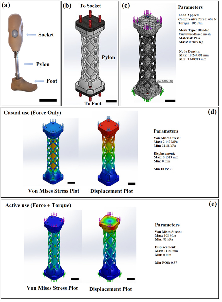
Overview of prosthesis design and finite element analysis. (a) A lower limb prosthesis including socket, pylon, and foot, (b) CAD model of a pylon, (c) the configuration of the setup on the material, mesh, and load, and (d) finite element analysis results for casual use, (e) finite element analysis results for active use. Scale bar: (a) 20 cm, (b–e) 3 cm. FOS: factor of safety.
Polylactic acid (PLA) and acrylonitrile butadiene styrene (ABS) are among the most used inexpensive polymer materials for 3D printing. PLA is made of organic materials such as cornstarch and sugarcane which makes it a biodegradable thermoplastic. It has been known as a bioplastic for many applications from plastic cups to therapeutic implants [14]. PLA is known by its inherent brittleness, a result of its molecular structure that restricts chain mobility and leads to lower impact resistance compared to more ductile polymers. Although this brittleness can pose challenges in applications demanding high flexibility or mechanical durability, it is not necessarily a drawback in all contexts. In biomedical applications, such as prosthetic devices, the brittleness of PLA does not compromise the structural integrity or functional performance of the device, making it a suitable and effective material choice for this application [15–17]. ABS is a well-known thermoplastic in the injection molding industry. It has been utilized in the manufacturing of LEGO, electronic housings, and vehicle bumper parts [18]. ABS has a glass transition temperature (Tg) at around 105°C which is higher than that of PLA (60°C). As a result, in those applications with a high temperature close to 60°C, the PLA structural integrity can be altered and the part can be deformed [19]. However, lower Tg means that PLA can be printed faster and easier than ABS. Although the tensile strength is low, the number is still high enough to provide the required mechanical strength for prosthetic applications and is safe to be used for medical purposes [20].
Several studies have been performed to show the usefulness of PLA in the manufacturing of 3D printed pylons. Tahir and Kadhim [7] reported the fabrication of 3D printed pylons using carbon fiber reinforced PLA filament. The fabricated prostheses were lighter and cheaper than traditional metal pylons; however, not all the required mechanical tests were performed to show the compliance of the 3D printed pylons with the ISO 10328 standard. Naiyf et al. [21] used PLA as filament for 3D printed pylons. Their results showed that the 3D printed pylon had enough strength under stress and acceptable safety factor to bear a high patient load without buckling compared to metallic prosthetic pylons; however, no cyclic compression test or torsion test was performed on the 3D printed pylons. In our previous study [13], we investigated the potential of 3D-printed pylons to be used in lower limb prosthetic devices. In that design, the stem of the pylon was connected to the base using bolts. Although the 3D printed pylons could partially comply with the requirements of the ISO 10328 standard, a long linear crack was developed at the location of the bolt due to the material discontinuity and stress concentration [13]. It was found that the base and stem of the pylon should be manufactured in one piece to prevent stress concentration at the joints.
The microstructure of 3D printed parts has a significant effect on the mechanical properties of the material, such as its strength and stiffness. Printing process, post-processing techniques, the orientation of the printed layers, and the presence of support structures also affect the mechanical properties of 3D printed parts [22]. Voids can weaken the material and reduce its overall performance. Despite technological advances, void presence in 3D printed parts remains unknown [23]. Microstructural models, such as a representative volume element (RVE), can model the microstructure in a finite element analysis (FEA) study to calculate the overall mechanical properties of the material based on the properties of the individual elements [24]. Another computationally intensive approach is to use discrete element model (DEM), to represent the microstructure of the material by modeling each individual void or other microstructural feature as a separate element. However, these modelling methods cannot capture all the variables and complexity of the 3D printed parts.
Currently, 2.1 million people are living with limb loss in the United States, which is expected to double by 2050 [25]. Below-knee amputations are the most common, representing 71% of dysvascular amputations. Having a robust design for 3D-printed prosthetic devices decreases the final cost of the product and alleviates the financial burden on amputees. In this study, we were inspired by the architecture of Euplectella aspergillum sponges. They offer a unique lattice microstructure with excellent mechanical properties as described in our previous studies [26, 27]. New designs, including a central cylinder and a circumferential lattice structure, were developed and tested to reduce the concentrated stresses on the pylon and to comply with the ISO 10328 standard.
A lower-limb prosthesis obtained from a patient was used for this study to produce the 3D-printed pylons (Figure 1a). Commercial software such as Ansys®/2021R1 and SolidWorks®/2022, has been utilized to perform FEA simulations. FEA simulations modeled torsion and compression tests from the standardized tests in the ISO 10328 standard to compare different computer aided design (CAD) models [28]. Factor of safety (FOS) is defined as the ratio of the failure load of a structure to the maximum working load that may be applied [29]. The FOS in the range of 1.7 to 3.7 is required according to the standard and what was considered for this study [28]. Additionally, our design utilized the P5 load tolerance outlined in the standard [28] to test the pylon, which corresponds to individuals with a maximum body weight of 125 kg and a very high activity level.
In this study, FEA was used as a screening tool to compare different designs before the physical testing. Although PLA printed via fused deposition modeling (FDM) exhibits anisotropy due to layer orientation, infill, and manufacturing parameters, to limit the complexity of the FEA study, 3D printed parts were assumed to have isotropic PLA material properties. Mesh sensitivity analysis was performed. Adaptive mesh refinement for both element order and size was controlled by the FEA software. A curvature-based meshing with a mech parameter of 1.82 cm for the maximum mesh size was used as the best mesh configuration. Approximately 20,049 nodes and 10,984 elements with a minimum edge length of 0.026 cm were used to perform the FEA studies.
After finalizing the initial designs and confirming their performance by FEA using SolidWorks software and Ansys, samples were 3D printed using a FDM 3D printer (MakerBot Replicator Z18, United States). Standard MakerBot PLA filament has been used for 3D printing the parts. Pylons were 3D printed vertically (samples were printed with the orientation shown in Figure 1b). It has been found that samples 3D printed longitudinally show higher mechanical properties compared to those printed in vertical direction [30]; however, due to the size of the pylons and the size limitation of the building platform in MakerBot Replicator Z18 printer, vertical orientation was selected. There is a trade off between the infill percentage and the weight of the pylons. Various infills (10% to 100%) were used to optimize the mechanical properties and weight of pylons. The speed of nozzle was set to 20 mm/s. For each test, 3 samples were used. PLA is less toxic and can be degraded in nature compared to ABS plastic, and it has negligible contraction during the cooling process [31–33]. Printing supports were used to print the samples precisely. After the printing process was finished, these supports were removed from the pylon before further testing. Table 1 shows the designation and various features of different samples.
Designation and specification of different samples.
| Designation | Infill percentage (%) | Core radius (mm) | Net radius (mm) |
|---|---|---|---|
| A10 | 10 | 10.15 | 2.22 |
| A25 | 25 | 10.15 | 2.22 |
| A30 | 30 | 10.15 | 2.22 |
| A50 | 50 | 10.15 | 2.22 |
| A70 | 70 | 10.15 | 2.22 |
| A90 | 90 | 10.15 | 2.22 |
| A100 | 100 | 10.15 | 2.22 |
| B2 | 25 | 10.15 | 4.25 |
| B3 | 25 | 10.15 | 6.66 |
Servo hydraulic universal testing machine (MTS) System model 370.50 with MTS 647 hydraulic wedge grip was used to determine the compressive strength of the samples. MTS test Suite Twelite software connected to the MTS Machine was utilized to gather the data and analyze the samples. Testing was performed as outlined in the ISO 10328 standard [28]. Bridge-bearing pads were utilized to hold the samples safely in place. For the static-proof compression test, the samples were firmly gripped on the wedge grips, and then the entire area was covered with a projectile-proof glass to prevent any damage due to the shattered parts.
As outlined in the ISO 10328 standard [28], a force was applied to the samples until they reached the settling test force (Fset) of 1,024 N. The Fset was maintained for a set duration of 30 s. The samples were then allowed to rest for 20 min. A stabilizing force, Fstab of 50 N, was loaded onto the samples and incrementally increased until it reaches 2,240 N at a rate of 1 mm/min. Upon reaching 2,240 N, the force was maintained for another 30 s. The force was then removed before the samples were taken off the testing setup. Permanent deformation of the samples was recorded, and the samples were considered to pass the test if the permanent deformation measured did not exceed 5 mm. Any cracks and failures that occurred during the testing were recorded and considered in labeling a sample as a failed/passed sample.
As outlined in the ISO 10328 standard [28], the following are the procedures required for the ultimate static strength test. The samples were firmly gripped on the wedge grips before the surrounding was protected by a projectile-proof glass to prevent any unwanted incidents. Force was then applied to the samples until it reached the settling force, Fset of 1,024 N. The Fset was maintained for a set duration of 30 s. The samples were then allowed to rest for 20 min. A stabilizing test force (Fstab) of 50 N was loaded onto the samples and incrementally increased until it reached 4,480 N or until the samples broke or failed at a rate of 1 mm/min. The samples were considered to pass the test if they reached 4,480 N without generating any defects.
The torsion test was performed according to the instructions outlined in the ISO 10328 standard [28]. One end of the samples was fixed on a wedge grip, while the other end was subjected to a twisting moment of 3 Nm for a period between 10 s and 30 s. The moment was removed, and the samples were allowed to rest for 20 min. The sample was loaded onto the testing equipment again and was exposed to a stabilizing twisting moment of 1 Nm. The original position of the sample was recorded with a line. The twisting moment was then increased at a rate of 2.5 Nm/s until it reached a maximum twisting moment of 50 Nm. This moment was then maintained for 30 s, and then the twisting moment was again decreased to the stabilizing twisting moment of 1 Nm. While holding the stabilizing twisting moment, the angular movement along the axis of twisting was measured. The sample passes the test if it is able to support the maximum twisting moment for 30 s, and its angular movement does not exceed 3 degrees. If the sample passed the test, then the test was repeated with a twisting moment in the opposite direction, with the same criteria.
The cyclic compression test was performed according to the ISO 10328 standard [28]. All tests were performed at room temperature. When the samples were loaded into the testing equipment, the Fset was applied for 30 s. The samples were then allowed to rest with zero load for 20 min. The samples were then subjected to the Fstab of 50 N. Then the force was increased to the maximum test force of 1,330 N. After that, the force was decreased to the minimum test force of 50 N, and then the sample was exposed to the cyclic loading with the forces varying between the maximum and the minimum test force. The prescribed number of cycles was 3 million cycles. The cyclic forces were applied in a sinusoidal waveform based on the following equations [34, 35]:
where Fc(t) is the test force, Fcmean is the mean test force, Fca is the amplitude of the pulsating test force, also known as the cyclic amplitude, ω is the angular frequency, and t is time. Fcmean is expressed as follows:
where Fcmax is the maximum test force, and Fcmin is the minimum test force. Also, Fca is defined as:
where Fcr is the range of the pulsating test force, also known as the cyclic range. The last equation, frequency (f), defines the speed at which the test is run:
The test force is a function of the average test force (690 N) plus or minus the time at which the force is being applied. The force applied varies as a sin curve, within the range of 50 to 1,330 N. The cyclic amplitude is the height from the mean test force (690 N) to either peak of the curve. Finally, the frequency of when the peak of each curve happens is 3 Hz. If the sample breaks while under cyclic loading, the breaking point is recorded.
Various samples were designed and evaluated by FEA for the manufacturing process. The initial design of the pylon with overall simulation configurations and a visual summary of the results is shown in Figure 1c–e. The results showed that the design passed the compression test, where the minimum FOS was 28, but did not pass the torsion test due to having a minimum FOS of 0.57. The core cylinder was designed to withstand the compression force, while the net architecture was incorporated into the design to improve the torsion resistance [26, 27]. This printing can only be used as a standard or relaxed application, rather than any active usage of the pylon. FEA provided us with insight to improve our design [36]. One of the parameters that should be considered in 3D printing is the infill percentage [37, 38]. In the next phase, the effect of various 3D printing infills was evaluated. Pylons were 3D printed and tested under compressive load. Only the ultimate static compression test was investigated. Static proof compression test, torsion, and cyclic compression tests were not considered when deciding on the infill percentage. This was due to the fact that both the static proof compression test and cyclic compression test mainly depend on the ultimate static compression test because the latter test is conducted to observe and record any failures that occur at the ultimate strength set by the ISO 10328 standard at 4,480 N. If the part fails in the ultimate static compression test, then there is no need to evaluate it by the static proof compression test and cyclic compression test. Furthermore, the torsion test mainly depends on the strength and design of the outer structure of the pylon, which is, in our case, the net. If the part passes the ultimate static compression test, then we evaluate the torsion behavior. The torque formula can be expressed as the follow [39]:
where T is torque (twisting moment), F is the applied force, and r is the radius of the pylon. Any twisting moment applied to the pylon was focused and maxed out on the outer radius. So, the net that resided on the outermost part of the pylon acts as the first layer of protection against the twisting moment. The objective of having the inner core was primarily to withstand compressive force; thus, strengthening the inner core could likely increase the chance of passing the ultimate static compression test as well as the cyclic compression test [32, 39]. With increasing the diameter of the core, the cross-sectional area of the core increases, which can significantly raise the amount of compressive strength. However, since the project focused on using 3D printing for each design, instead of changing the diameter of the inner core, we focused on changing the infill density of the initial design to determine the optimum percentage of infill. Printing an object at a low infill percentage decreases the printing time, but it also causes lower compression strength. Another main reason for exploring the possibilities of using different infill percentages was to reduce the overall weight of the pylon samples [40]. Based on our design specification, the finished product must have a lighter weight compared to the existing stainless-steel pylon (which was used as the control sample and a reference for our design), with a weight of 400 g. Reducing the infill percentage while the part can resist the ultimate static compressive strength test significantly reduces the weight of the pylon, thus decreasing the total cost of the product [41]. Various infill percentages were considered initially to evaluate the performance of the pylons (10%, 30%, 50%, 70%, 90%, 100%). An ultimate static compression test was first done on the design with 10% infill (sample A10). The maximum force loaded on the sample peaked at 3,564.725 N before the inner cylindrical core started to sink into the base of the pylon. After the load reached the peak, the outer net of the pylon broke, and consequently, the force dropped to around 2,000. The peak load observed in the 10% infill samples was below the requirement of the ISO 10328 standard (4,480 N). The low density causes the pylon to be hollow inside. The 10% infill reduced the amount of material inside the pylon, making it weaker in withstanding compression force [37, 38, 40, 41].
Using the results obtained from the initial test, we proceeded on the pylon with 50% infill (A50). The maximum compressive force of the A50 sample was 9,597.318 N, where the value was more than double the ultimate static test force needed in the ISO 10328 standard. By having more infill in the inner structure of pylons, a higher effective cross-sectional area was provided [37, 40]. As the load was increased on the sample, first the outer net broke (as reflected by the steady linear drop on the load-displacement curve). At the end of the test, the load drops down significantly until it reaches 0 N as a result of the failure of the cylindrical core. Figure 2 shows the load-displacement curve of A10 and A50 samples, as well as the maximum compressive strength of other pylons 3D printed with different infill percentages.
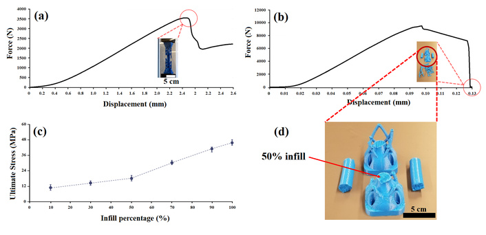
Mechanical characterization of pylon samples. Load-displacement graphs of (a) 10%, and (b) 50% infill; (c) ultimate compression stress of different samples; (d) the structure of 50% infill sample. Insert in (a) shows the broken net after the first drop in the load-displacement curve; insert in (b) shows the shattered sample of the pylon with 50% infill.
As seen in Figure 2c, the maximum compressive stress increased linearly from A10 to A50. In this project, we aimed to produce a lightweight 3D-printed pylon. Therefore, the samples with higher infill percentages were not tested for static-proof compression test and cyclic compression test. Samples with lower infill percentages were evaluated and optimized to make sure low-weight pylons can be produced [40, 41]. Based on the linear relationship between infill percentage and compressive strength, it was found that 25% infill should provide enough strength. Before 3D printing, FEA was performed to ensure that the design could pass the specific compression and torsion test set by the ISO 10328 standard [28]. In the FEA of all samples for the compression test, the ultimate static strength of 4,480 N was used as the compressive force to determine the safety factor. The setup for each analysis was performed by using a compressive force loaded on the top surface of the pylon, while the bottom surface was fixed. Figure 3 shows the results of the FEA of the samples. The FOS was 9.88, which was several times higher than the basic requirement of the ISO 10328 standard, which also indicates that the sample passed the compression test. FEA was also performed for torsion analysis. 50 Nm torque is required by the ISO 10328 standard. For FEA, torque was applied on the top surface while the bottom surface was fixed. The torsion was applied in both clockwise and counterclockwise directions. The FOS of this design was 0.85 when the torque of 50 Nm was applied. From the FOS value, the design structure would fail before the twisting moment of 50 Nm can be reached. The net layer acts as the protection structure for the cylindrical core of the pylon. Torsional stresses would be more distributed around the net structure instead of the cylindrical core.
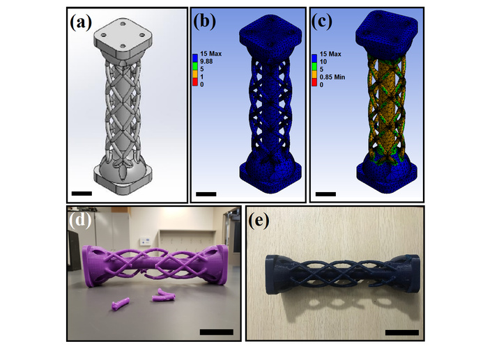
Mechanical characterization of sample A25. (a) SolidWorks model of A25, (b) FEA compression test data (MPa), (c) FOS in torsion test, (d) image of the broken A25 sample after the compression test, and (e) image of the broken A25 after the torsion test. In both samples, the net structure failed. Scale bar: (a–c) 3 cm, (d, e) 5 cm. FEA: finite element analysis; FOS: factor of safety.
Samples were tested to verify the compressive strength and torsional resistance under load. A25 passed the static compression test with a maximum force of 6,614 ± 736 N, which exceeded our target force of 4,480 N. The design did not meet the requirement of the torsion test because the pylon broke at 33.63 ± 7.3 Nm, which is below the ISO standard of 50 Nm. Figure 3d and 3e demonstrate the broken pylons after compression and torsion tests, respectively.
These results were in good agreement with the FEA results. It was found that the diameter of each individual net was not enough to resist torsion stresses. In developing the new designs, the factors affecting normal and shear stresses were considered [34]. To ensure models experience lower stresses, a large cross-sectional area, which also increases the moment of inertia, is required. The design had a proper cylindrical core to resist compression forces. The maximum shear will occur at the outermost edge of the pylon. Consequently, increasing the net thickness provides higher resistance under torsional stresses.
Sample B2 was designed and then evaluated by FEA (Figure 4). The lowest FOS of this sample was 2.69 when the compression force of 4,480 N was applied, which passed the ISO 10328 static compression test. Also, in torsion analysis, the torque was applied on the top surface while the bottom surface was fixed. The torsion was applied in both clockwise and counterclockwise directions. The FOS of the torsion test was 2.15 when the torque of 50 Nm was applied, which met the requirements of the ISO 10328 standard (Figure 4a and 4b). The design passed the static compression test with a maximum force of 7,901 N, which exceeds our target force of 4,480 N. Also, the design passed the torsion test with 50.63 Nm with deformation at 1.03 degrees clockwise and 2.06 degrees in the counterclockwise direction on the pylon. As seen in Figure 4c, the design failed at the cyclic compression test with 0.38 million cycles, which was below the 3 million cycles required by the ISO 10328 standard. Therefore, in our final design (sample B3), we increased the radius of the net from 4.25 mm to 6.66 mm, and then the tests were repeated.
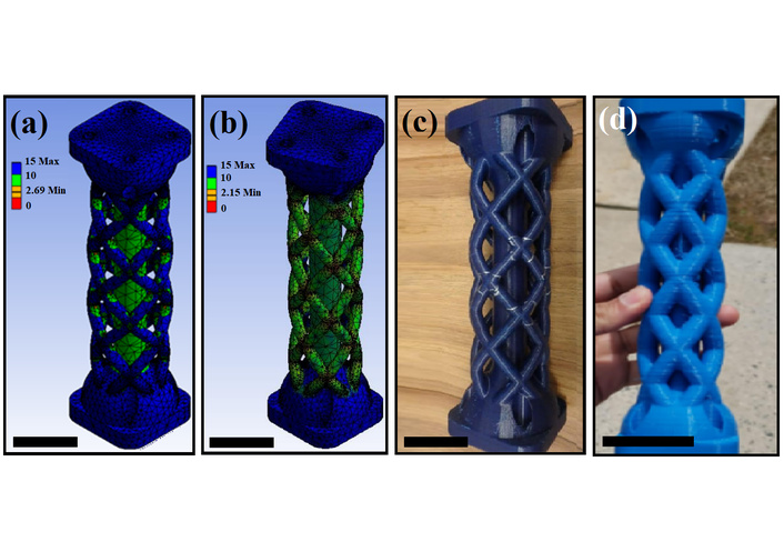
Mechanical testing and structural evaluation. (a) FOS in compression test (B2), (b) FOS in torsion test (B2), (c) image of the 3D printed pylon after cyclic compression test (B2), the cracks on the net were generated during the cyclic compression test, and (d) image of the 3D printed pylon (B3), which met all the requirements of the ISO 10328 standard tests. Scale bar: 5 cm. FOS: factor of safety.
The cyclic test was repeated for B3 for more than 15 days. The specimen had achieved 3 million cycles. No crack was observed on the samples (Figure 4d). B3 successfully passed the requirements of the ISO 10328 test. The metal pylon in Figure 1a can be replaced by the 3D printed pylons with the net radius of 6.66 mm. The results showed that proper design can decrease the weight and cost of the prosthesis. The weight of B3 sample was 282 g which was about 30% less that the metal one (400 g for the pylon in Figure 1a). Also, metal pylons will cost more compare to 3D printed pylons. Lower limb prosthesis price starts from $3,000 and can increase drastically based on the functionality and applications [42, 43]. The cost of the initial materials for the 3D printed pylons investigated in this study was around $6 which is extremely lower than used pylons available in the market (~$100) [7]. It is important to note that PLA pylons degrade over time, with their degradation rate being significantly influenced by factors such as molecular weight, crystallinity, temperature, mechanical stress, and humidity [44, 45]. Given the low production cost of 3D-printed PLA pylons and the capability to manufacture them in remote or resource-limited healthcare settings, they present a viable alternative to traditional metal pylons. Additionally, in the current design, the outer mesh structure of the pylon is engineered to fail before the inner core. This feature serves as an early-warning indicator, allowing timely detection of structural compromise and facilitating appropriate replacement before complete failure occurs. Table 2 shows a summary of the samples that passed or failed based on the ISO 10328 standard in different tests.
Mechanical testing evaluation of various samples.
| Samples | Ultimate static strength test | Torsion test | Static proof test | Cyclic compression test |
|---|---|---|---|---|
| A10 | Failed | - | - | - |
| A25 | Passed | Failed | - | - |
| A30 | Passed | Failed | - | - |
| A50 | Passed | - | - | - |
| A70 | Passed | - | - | - |
| A90 | Passed | - | - | - |
| A100 | Passed | - | - | - |
| B2 | Passed | Passed | Passed | Failed |
| B3 | Passed | Passed | Passed | Passed |
In this study, 3D printed pylons were designed, analyzed, and tested according to the ISO 10328 standard for application in the prosthetic device. Various designs were generated and analyzed by FEA. A cylindrical core was designed and centered on a lattice structure. The centered cylinder generated the required strength to resist compression force, while the lattice structure provided the required strength to resist torsional moments. It was found that 25% infill is enough for the 3D printed pylons to provide enough compressive strength. The radius of the net structure should be 6.66 mm to resist torsional moments. The results showed that a simple 3D printer can be used to manufacture pylons that meet the requirements of the ISO 10328 standard. For future studies, the effect of moisture and humidity on the long-term mechanical performance of these pylons should be considered. Furthermore, the impact of various 3D printing materials on the weight, cost, and performance of these pylons can be studied. 3D printing technique indeed can provide a simple yet effective and inexpensive method to manufacture prosthetic devices and alleviate the financial burden on amputees.
ABS: acrylonitrile butadiene styrene
FDM: fused deposition modeling
FEA: finite element analysis
FOS: factor of safety
Fset: settling test force
Fstab: stabilizing test force
PLA: polylactic acid
Tg: glass transition temperature
The authors would like to appreciate the help and support from the Smithers company for assisting us with performing some tests. The company had no role in study design, decision to publish, or preparation of the manuscript.
FT: Conceptualization, Methodology, Investigation, Resources, Writing—original draft, Writing—review & editing, Visualization, Supervision, Project administration, Funding acquisition. NKK: Methodology, Validation, Formal analysis, Investigation, Writing—original draft, Visualization. MSMY: Methodology, Validation, Formal analysis, Investigation, Writing—original draft, Visualization. LHIN: Methodology, Validation, Formal analysis, Investigation, Writing—original draft, Visualization. FHM: Methodology, Validation, Formal analysis, Investigation, Writing—original draft, Visualization. AA: Methodology, Formal analysis, Investigation, Writing—review & editing, Visualization, Supervision. All authors read and approved the submitted version.
The authors declare that they have no conflicts of interest.
Not applicable.
Not applicable.
Not applicable.
The raw data supporting the conclusions of this manuscript will be made available by the authors, without undue reservation, to any qualified researcher.
This project was partially supported by the NSF-CAREER under the NSF Cooperative Agreement CMMI-2146480. The funder had no role in study design, data collection and analysis, decision to publish, or preparation of the manuscript.
© The Author(s) 2025.
Open Exploration maintains a neutral stance on jurisdictional claims in published institutional affiliations and maps. All opinions expressed in this article are the personal views of the author(s) and do not represent the stance of the editorial team or the publisher.
Copyright: © The Author(s) 2025. This is an Open Access article licensed under a Creative Commons Attribution 4.0 International License (https://creativecommons.org/licenses/by/4.0/), which permits unrestricted use, sharing, adaptation, distribution and reproduction in any medium or format, for any purpose, even commercially, as long as you give appropriate credit to the original author(s) and the source, provide a link to the Creative Commons license, and indicate if changes were made.

View: 4446
Download: 60
Times Cited: 0
Minhaz Husain ... J. P. Davim
Bharat Kalia ... Gurwinder Singh
Antonio Ziranu ... Greta Tanzi Germani
Apurba Das, Pradhyut Rajkumar
Joshua D. Smith ... Matthew E. Spector
Frank Traub ... Felix Wunderlich
